
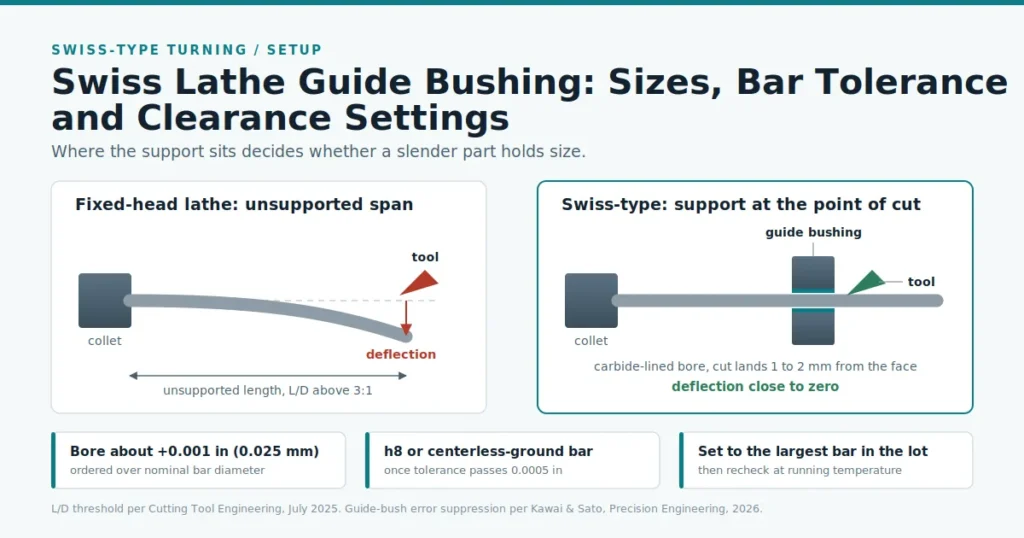
The swiss lathe guide bushing supports the bar stock at a distance of one to two millimeters from the cutting point, eliminating the cantilever effect that causes the slender workpiece to bend. According to the nominal diameter of the bar, the inner hole of the guide bushing is placed about 0.001 in (0.025 mm) in order, which is used with H8 grade or centerless polished bar. Then use the bar with the largest diameter in the same batch to tighten the guide bushing until a slight block can be felt when the bar is rotated by hand.
If the parts are scrapped, the problem is not necessarily in the blade. When the bar processing is halfway through, if the Z-axis load is found to continue to rise, the size problem on the sliding-headstock machine often originates before the tool. The following three factors largely determine the processing results: which type of guide bushing is installed in the guide bushing seat, which spring series is used in the machine tool, and how much clearance is left between the inner hole of the guide bushing and the bar.
What a Swiss Lathe Guide Bushing Actually Controls?
The guide bushing of the Swiss lathe firmly supports the bar in the position close to the cutting point, so that the radial force acts directly on the support point, rather than on the end of the lever away from the support. In July 2025, “Cutting Tool Engineering” reported that this structure is truly cost-effective on parts with a length-to-diameter ratio of at least 3 : 1 or 4 : 1.
Below this ratio, fixed-headstock lathes tend to use less tuning time to complete the processing. Above this ratio, the deflection will increase rapidly, because the bending amount under lateral load is proportional to the cubic of the unsupported length.
The supporting role is not only to resist bending. In a 2026 “Precision Engineering” paper, Kawai and Sato established a model for all geometric errors in the structural loop of the walking center automatic lathe. The results show that the guide bushing can be passed before the error is passed to the cutting point. The position error and angle error of the spindle centerline, as well as the workpiece clamping error are forced to be corrected.
This amendment also defines its limitations. The guide bushing can only truthfully reflect the original shape of the bar: a non-circular bar rotates in the circular hole, and the final processed part will be non-circular. This constraint should be taken into account as soon as possible when comparing the sliding-headstock CNC lathe with the fixed-head turning center.
Rotary, Fixed and Adaptive Guide Bushing Types
The rotary guide bushings rotate with the bar, which is suitable for most batch production. The fixed guide bushing is kept static for machining tasks with higher precision requirements. In its 2026 Guideline for bushings, the Absolute Machine Tools set the dividing line near ± 0.0005 in: Tolerances above this value are required to be rotary and below this value are required to be fixed.
The rotary guide bushing unit is installed on the bearing, and the relative sliding between the bar and the inner hole is almost reduced to zero. This helps to protect the surface quality and also reduces the ghost threading scratches that are common in the workshop. The cost is the introduction of bearing clearance, so for the most stringent processing tasks, the fixed guide bushing will be used instead.
The fixed guide bushing provides the highest position stability and can achieve the smallest inner hole diameter. The price is friction. The bar rotates directly against the inner hole at full speed, so the easy-to-cut materials and sufficient cutting oil flow have become a necessary condition from an optional one.
The adaptive guide bushings are between the two. Its biconical elements operate at a constant pressure, allowing the inner hole to be adjusted with the bar size rather than being forced to constrain the bar, thus making it possible to use cold drawn bars.
High-quality products are generally lined with cemented carbide. There are some circular guide bushings with cemented carbide lining, the purpose is to keep the bar surface clean and traceless. Before purchasing the guide bushing and its seat, you should consider the tolerance requirements to determine guide bushings type.
| Rotary | Fixed | Adaptive | |
|---|---|---|---|
| Bar/bore motion | Bushing spins with bar | Bar spins in static bore | Bore follows bar |
| Tolerance fit | Looser than ±0.0005 in | ±0.0005 in and tighter | Mid-range |
| Stock required | Ground preferred | Ground, free-machining | Drawn acceptable |
| Main drawback | Bearing play | Friction, heat | Added complexity |
Swiss Lathe Collet Series & Guide Bushing Sizes
The serial code represents the machine tool category, not the bar diameter. According to the comparison table updated by Forkardt Hardinge in December 2025, TF16 clip spring and SD125 R guide bushing are used for 12 mm machine tools, and TF37 SP and TD32 are used for 32 mm machine tools. Before leaving the factory, each product is tested on the full run-out (TIR) spindle with a run-out requirement of 0.000015 in.
In the same series, the only change is the size of the ordered bore. A TF25 body can cover a range of bar diameters, and the specific aperture is specified by the user. The series depends on the machine tool, and the aperture depends on the bar.
The machine specification determines the upper limit of the diameter of the bar that can be machined. “Cutting Tool Engineering” July 2025 lists the index spindle feed hole diameter: TNL12 is 13 mm, TNL20 is 20 mm, TNL32 is 32 mm.
Each machining task needs to focus on four clamping positions: spindle clamp spring, guide bushing, sub-spindle (receiving) clamp spring, and ER cylinder clamp on the tool side. The commonly used specifications are ER11 to ER25. Our clamp spring and guide bushing comparison table lists common pairing combinations by machine model.
| Machine class | Headstock colle | Guide bushing | Pick-off collet |
|---|---|---|---|
| 10 mm | TF15 | TD10 | TF8 |
| 12 mm | TF16 | SD125R | TF16 |
| 16 mm | TF20/TF25 | 201 | TF20 |
| 20–26 mm | TF25/TF30 | TD25-NS/CD25 | TF25/TF30 |
| 32 mm | TF37/TF37SP | TD32/TD32S | TF37SP |
Bar Stock Tolerance: What h7, h8 and h9 Buy You
The size fluctuation of the rod determines the size of the gap that can be maintained. According to ISO 286-2, a 16 mm bar with a diameter of 43 μm smaller than the nominal size at the h9 tolerance level; h8 reduces the tolerance zone to 27 μm, and H7 further reduces it to 18 μm. If the guide bushing is tightened according to the upper limit size of a batch of h9 bar, the gap will be too large when the bar is processed to the lower limit size in the batch.
Straightness is as important as diameter. Tyler Economan, Sales Manager of Index Technology, told “Cutting Tool Engineering” in July 2025 that the bar must be straight enough to pass through the guide bushing smoothly, which is the reason why polished bar and center processing usually need to be used together.
Centerless grinding of rod or screw-machine quality rod can eliminate the diameter difference between batches that force the operator to readjust the guide bushing during processing. Although this bar is more expensive per kilogram, it can save costs in terms of shunting time, guide bushing life, and scrap rate, thereby offsetting additional expenses.
There are also alternatives. The switchable model can remove the guide bushing and process the cold drawn bar in chucker mode. The same 2025 report gives a replacement time of 10 to 15 minutes for the Index model and about 10 minutes for Marubeni Citizen-Cincom, and unsupported processing is feasible within a length of about 50.8 mm.
| Nominal Ø | h7 | h8 | h9 | h11 |
|---|---|---|---|---|
| >6-10 mm | 15 | 22 | 36 | 90 |
| >10-18 mm | 18 | 27 | 43 | 110 |
| >18-30 mm | 21 | 33 | 52 | 130 |
| >30-50 mm | 25 | 39 | 62 | 160 |
According to the required mode of parts processing, the feeding machine and bar pretreatment scheme are configured.
How to Set Swiss Lathe Guide Bushing Clearance?
Most workshops will order the inner hole of the guide bushing according to the nominal size of the bar about 0.001 in (0.025 mm), and then use the bar with the largest diameter in the same batch to tighten. In October 2025, Nomura DS pointed out that too tight guide bushings would cause the inner hole to be unable to obtain cutting oil, which is why the tight fit developed into stuck.
The setting steps are not complicated:
- 5 to 10 bars were taken from the same batch, and the maximum diameter was measured and recorded with a micrometer.
- Use the bar with the largest diameter to set the guide bushing, not according to the average diameter.
- Tighten the guide bushing until the bar cannot rotate, and then roll back according to the amount specified by the machine tool manufacturer.
- Hand inspection: The bar should be able to rotate with a slight sense of retardation, while still freely advancing and retreating.
- After the machine reaches the operating temperature, review the gap again.
The final step is the most easily overlooked. The thermal effect accounts for 40% to 70% of the total error of the machine tool, and their walk-center test device is based on the end face of the guide bushing as the measurement benchmark. The gap set in a cold state is not equal to the gap in actual operation.
| Signal | Too tight | Too loose |
|---|---|---|
| Z-axis load | Climbing | Normal |
| Surface | Ghost threading, marring | Chatter marks |
| Dimensions | Length drift from compression | Roundness and taper drift |
| Failure mode | Seizure, stuck bar, tool breakage | Vibration, poor finish |
Log the setting against the bar lot. Operators develop a feel for the wrench, but feel does not transfer between shifts. A recorded number does, and it shortens the next changeover on your Swiss machine setup and maintenance checklist.
Conclusion
Guide bushing performance is a chain. Machine class picks the collet series, bar grade sets the achievable clearance, and clearance decides whether you get chatter, a seizure or a good part. Order the bore near 0.001 in over nominal, specify h8 or ground stock once tolerances pass ±0.0005 in, set against your largest bar, and recheck warm. Skip any link and the other three stop protecting you.
FAQ
It supports the bar at a distance of one or two millimeters from the tool, so that the cutting force acts on the support point, rather than on a stretch. This structure is suitable for parts with a length-diameter ratio of 3 : 1 and above, and the fixed spindle box lathe will produce deflection deformation on such parts.
There is a slight sense of retardation when the bar is rotated by hand, and the bar can still slide and return when it is loose. Too tight will block the cutting oil into the inner hole. Set the thickest bar of the batch, and review it again after the machine is hot.
Rotary assembly on the bearing rotates with the bar to reduce friction and surface scratches ; the fixed type remains stationary, and the bar rotates in the inner hole. Absolute Machine Tools sets the 2026 boundary near ±0.0005 in, with looser rotary options and fixed options when tolerances or diameters become smaller.
Yes, on a switchable model. “Cutting Tool Engineering” reported in July 2025 that the replacement time of Index is 10 to 15 minutes, Marubeni Citizen-Cincom is about 10 minutes, and unsupported parts are feasible within a length of about 50.8 mm. Longer work still needs to be fitted back to the guide bushing.
The series is taken from the machine model, and the inner hole is taken from the bar. The comparison table of Forkardt Hardinge December 2025 uses TF16 with SD125R for 12 mm machine tools and TF37SP with TD32 for 32 mm machine tools. The inner hole is generally ordered according to the nominal diameter of the bar about 0.001 in.