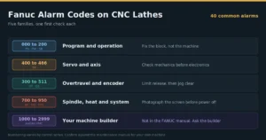

Fanuc alarm codes are numbered fault messages that tell you which subsystem stopped the machine, not what actually broke. On CNC lathes they fall into five families: program (PS), parameter (PW), servo (SV, 400s), overtravel and encoder (OT and DS, 300s and 500s), and spindle or system (SP, SYS).
| Number on screen | Family | Jump to |
|---|---|---|
| 000 to 200, or PS, PW, SR | Program and operation | Section 2 |
| 400 to 466, or SV | Servo and axis | Section 3 |
| 300 to 511, or OT, DS | Overtravel and encoder | Section 4 |
| 700 to 950, or SP, OH, SYS | Spindle, heat, system | Section 5 |
| 1000 to 2999 | Your machine builder, not Fanuc | Section 5 |
Introduction
When the spindle stops running, the screen shows a red alarm message, and the workpiece is still stuck in the chuck. You don’t need all 400 alarm codes listed in the manual, but focus on three things: which category the alarm code belongs to; whether the alarm can be eliminated after pressing the reset key (RESET); and whether it is safe to open the electrical cabinet at present. This article covers the 40 Fanuc alarm codes most commonly encountered on CNC lathes.
Safety Notes: After disconnecting the main power supply, the DC link capacitor of the servo amplifier will still retain the dangerous charge within a few minutes. When the power supply is restored, the chuck, tailstock or sliding spindle box may act. Before opening the electrical cabinet, perform a lockout/tagout and use a reliable instrument to confirm that the device is in a zero-energy state. If some steps require live measurement, and you do not have the appropriate qualifications, you should stop the operation. Nothing in this article can replace the maintenance instructions corresponding to your machine tool and system.
How to Triage Fanuc Alarm Codes in Under 60 Seconds?
Before pressing the reset key, check the alarm history first, because the first record is usually the cause of the alarm, and the next few are the associated results caused by it. Then decide if you need to open the electrical cabinet.
Work the sequence in this order, every time:
- Copy down the complete number and information text, which axis is marked in the text.
- Open the alarm resume screen to find out the first of this series of alarms.
- Use the above table to determine which family category the alarm belongs to.
- First check the reasons for easy investigation and low cost: air pressure, way lubricating, chip remover jamming, filter screen, connector loosening, and incoming line voltage.
Only then substitute parts, one at a time. Operators new to sliding headstock machines will find the mechanical context in this walkthrough of how a CNC Swiss lathe feeds bar stock past the tool.
Old numbers and new prefixes: reading both formats
Series 0, 0i-A, 0i-B, 16, 18, 21 controls display a bare three digit number. Series 0i-D, 0i-F, 30i, 31i and 32i add a two letter prefix and pad to four digits. Alarm 401 and alarm SV0401 describe the same fault.
| Prefix | Family | Older equivalent |
|---|---|---|
| PS | Program and operation | 000 to 255 |
| PW | Parameter change, power cycle needed | 000, 100 |
| SR | Serial input and output | 085 to 087 |
| SV | Servo | 400 series |
| OT | Overtravel | 500 series |
| DS | Absolute encoder and detection | 300 series |
| SP | Spindle | 700 series |
The mapping is a guide, not a guarantee. Numbering shifted between generations, so match the on screen wording rather than assuming the number carried over unchanged.
Fault first: where to look before you look up the number
| What you actually see | Family to check | First move |
|---|---|---|
| No motion at all, drives never enable | Servo, power | E-stop chain, amplifier LEDs |
| Alarm the instant the spindle starts | Power quality, spindle | Measure incoming voltage under load |
| Axis stops mid cut, number in the 400s | Servo | Read diagnostic bits before ordering parts |
| Turret jogs one way but not the other | Overtravel | Hold limit release, jog the opposite way |
| Alarm after a weekend shutdown | Encoder battery | Test battery, then re-reference |
| Program halts at the same block every run | Program | The block is the fault, not the machine |
Program and Operation Alarms (PS and PW): 10 Codes You can Usually Clear
Most Fanuc alarm codes in this type of alarm are setup errors rather than hardware failures, but both cause the same downtime. In 2025, a survey of 3,600 industrial policymakers by ABB and Sapio Research found that 44% of people experience equipment-related downtime at least once a month, and 83% believe that losses exceed $ 10,000 per hour.
| Code (old/new) | What it points at | Likely cause on a lathe | Clearing it |
|---|---|---|---|
| 000/PW0000 | Change takes effect only after a power cycle | Parameter or servo setting edited | Power down, power up |
| 010/PS0010 | Commanded G code unavailable on this control | Wrong post, or option not purchased | RESET |
| 011/PS0011 | No feedrate for a cutting move | F missing, or G98 and G99 mixed up | RESET |
| 020/PS0020 | Arc endpoint and radius disagree | Rounded corner geometry out by microns | RESET |
| 041/PS0041 | Nose radius compensation would gouge | G41 or G42 into a groove narrower than the insert nose | RESET |
| 059/PS0059 | Called program number not found | O number lost during a DNC transfer | RESET |
| 070/PS0070 | Not enough program memory | Years of old programs never deleted | Delete, then RESET |
| 085/SR0085 | Serial input overrun | Baud rate or parity mismatch on the DNC link | RESET |
| 090/PS0090 | Reference return could not complete | Axis started too close to the mark, or feedback too slow | Jog clear, retry |
| 100/PW0100 | Parameter write still switched on | PWE left at 1 after editing | Set PWE to 0, RESET |
In addition, there is a related code to be explained. Alarm 224, which is displayed as PS0224 on a newer system, will prohibit cyclic start-up before all axes are completed back to the reference point. This is not a failure, but the system refuses to start the program from an unknown location. Operators still building confidence on sliding headstock machines will find more groundwork in this Swiss machining questions and answer guide.
Servo and Axis Alarms (SV, 400 Series) on Turning Centres
Servo Fanuc alarm codes name the axis that noticed a problem, not the part that failed. Check mechanics before electronics. In 2025, a study in the journal Lubricants (Zhang, Huang and Sun, volume 13, issue 8) built CNC feed system fault diagnosis around bearing vibration, showing how often axis faults start in the drivetrain.
| Code (old/new) | What it points at | Likely cause on a lathe | Clearing it |
|---|---|---|---|
| 401/SV0401 | Amplifier ready signal dropped out | E-stop chain, MCC, incoming supply sag, FSSB order | Find the cause first |
| 404/SV0404 | Ready signal present when it should be off | Welded contactor tip, amplifier or wiring fault | Service |
| 409/SV0409 | Abnormal load detected on an axis | Crash, seized ballscrew, dull tool jammed in the cut | Inspect, then RESET |
| 410/SV0410 | Position deviation too large while stopped | Brake not releasing, mechanical bind, low gain | Inspect mechanics |
| 411/SV0411 | Position deviation too large while moving | Way lube starvation, chips packed in a slideway | Check lube first |
| 414/SV0414 | Digital servo detection system fault | Encoder, encoder cable, amplifier, overheat | Read diagnostic bits |
| 417/SV0417 | Servo parameter outside its valid range | Bad restore after a board swap | Compare to backup |
| 430/SV0430 | Servo motor overheat | Sustained heavy cutting, blocked cooling, failed thermostat | Cool down, find cause |
| 436/SV0436 | Software thermal overload | Repeated overload the motor survived but the control counted | Reduce duty, inspect |
| 466/SV0466 | Motor and amplifier ratings do not match | Wrong replacement part fitted | Verify part numbers |
Alpha and Beta series amplifiers also give an alpha code on their own monitors. HCAL indicates motor or cable short circuit, HVAL indicates DC bus overvoltage, LVAL indicates power supply problem, DCAL indicates regenerative resistance, FBAL indicates feedback line disconnection. This letter code is usually more specific than the digital alarm on the system. Regarding the reason why the shafting layout of different models is different, we can refer to the design difference between this Swiss-type and traditional lathe.
Overtravel and Encoder Alarms (OT and DS, 300 and 500 Series)
The overtravel alarm is that the protection function is working, and it can stop the movement before the knife tower hits the bed. ISO 23125 is a class C safety standard for turning machine tools, which will continue to be effective after review in 2024. The standard regards the travel limit as a design protective measure, rather than an interference that can be turned off.
| Code (old/new) | What it points at | Likely cause on a lathe | Clearing it |
|---|---|---|---|
| 300/DS0300 | Absolute encoder needs a reference return | Battery replaced, or encoder cable disturbed | Re-reference the axis |
| 306/DS0306 | Encoder battery at zero, position lost | Battery flat, or changed with power off | New battery, re-reference |
| 307/DS0307 | Encoder battery low, position still valid | Battery near end of life | Replace under power |
| 350/DS0350 | Serial pulse coder fault | Encoder failure or contamination | Service |
| 351/DS0351 | Pulse coder communication fault | Cable, shielding, grounding, connector | Wiring investigation |
| 500/OT0500 | Stored stroke limit exceeded, plus side | Wrong work offset, crash, lost reference | Limit release, jog back |
| 501/OT0501 | Stored stroke limit exceeded, minus side | Same causes, opposite direction | Limit release, jog back |
| 506/OT0506 | Hardware limit switch tripped, plus side | Ran past the switch, or the switch failed | Limit release, inspect |
| 507/OT0507 | Hardware limit switch tripped, minus side | Same, opposite direction | Limit release, inspect |
| 510/OT0510 | Next block would cross a stored limit | Stroke check before move caught it early | Correct the program |
Codes 506 and 507 are proprietary to the T-series lathe system, and technicians looking up according to the milling machine alarm list cannot find these codes. Developing two habits can prevent most of the problems in this category: one is to replace the encoder backup battery as planned under the energized state of the system; the second is to re-confirm the workpiece coordinate system after any collision. The X-direction stroke of the CNC lathe machine itself is short, so the accuracy of the guide sleeve setting and the coordinate system is particularly important. See Swiss lathe guide bushing clearance errors for the setup side of the same problem.
Spindle, Overheating and System Alarms (SP, OH and SYS)
This type of alarm is the most costly and dangerous part of judging errors. On June 27,2025, OSHA issued Directive CPL 03-00-027, which renewed the national key inspection plan for limb amputation accidents in the manufacturing industry for five years. The focus of the inspection is the energy control during machine tool protection and maintenance.
| Code (old/new) | What it points at | Likely cause on a lathe | Clearing it |
|---|---|---|---|
| 700/OH0700 | Control unit overheat | Blocked filter, failed cabinet cooler, hot shop | Clean, then cool down |
| 701/OH0701 | Cabinet fan motor fault | Bearing failure in the fan | Replace fan |
| 704/OH0704 | Spindle speed deviates from command | Belt slip, heavy cut, load meter pegged | Reduce load, inspect |
| 749/SP0749 | Serial spindle communication error in operation | Electrical noise, cable, poor cabinet earth | Wiring investigation |
| 750/SP0750 | Serial spindle link failed to start | Spindle amplifier not ready, fibre, parameter mismatch | Check amplifier first |
| 910/System alarm screen | Memory parity error in part program storage | Failing SRAM or a flat control battery | Service, restore backup |
| 920/System alarm screen | Servo watchdog or servo memory fault | Control board or servo card | Service |
| 930/System alarm screen | CPU interrupt | Board fault, or severe electrical noise | Service |
| 950/System alarm screen | PMC system fault | Ladder or PMC hardware | Service |
| 5136/SV5136 | Fewer amplifiers found than configured | Amplifier unpowered, broken fibre, FSSB order changed | Power all amps, check fibre |
The system alarm of 900 section is renumbered on 0i-D, 0i-F and 30i systems and displayed on a separate system alarm screen. Before the power off, take the picture first, because the details may not be written into the alarm resume.
The alarm number your FANUC manual does not list
If the alarm number is between 1000 and 2999, you no longer need to consult FANUC data. This segment belongs to the machine tool factory and is written into the PMC ladder diagram by Doosan, Hardinge, Tornos, Mazak or any of the companies that assemble the machine. The chuck loosening fault, tail seat interlock, turret indexing failure, feeder timeout, door interlock, all belong to this section.
The same number has completely different meanings on the machines of two different machine tool factories. The instructions of the machine tool factory should be used; if the instructions are lost, the alarm list can be requested from the manufacturer by the factory number of the machine tool. As for which model to choose at the beginning, you can refer to the selection comparison between this Swiss versus conventional CNC lathe.
FAQ
This can sometimes be eliminated, but the meaning of SV0401 is that the amplifier reports itself not ready, that is, a factor interrupts the ready loop. If reset without finding out the cause, it usually stops again later in the cutting process. For a CNC lathe powered by a rotary phase converter, the incoming line voltage should be measured first when the spindle is loaded.
The low voltage alarm, i.e., 307 or DS0307, indicates that the encoder backup battery power is reduced, but the absolute position is still valid, so the battery can be replaced under the energized state of the system to retain the reference position. The voltage is zero, that is, 306 or DS0306, indicating that the position information has been lost, and the shaft must be returned to the reference point to operate.
There are two reasons. The system of each generation has been renumbered, so the 401 on 0i-B is SV0401 on 0i-F, and the text expression is slightly different. In addition, every number between 1000 and 2999 is written by your machine tool factory itself, and these numbers are never common between different brands.
Switch to click or handwheel mode, hold down the override release button, remove the shaft from the limit, and then press reset. If the shaft has not yet returned to the reference point, some systems allow the key combination given by the machine tool manual to temporarily bypass the soft limit when powered on. Do not close the limit function for a long time.
No. It only indicates which subsystem detects the problem. The root cause is usually in the next layer: lubrication, alignment, cooling, power quality or a connector. The excessive position deviation in the movement of the alarm 411 is an example. The alarm is shown as a servo problem, but the cause is often the interruption of the guide rail lubrication.
*Trademark notice. FANUC is a registered trademark of FANUC CORPORATION. This website has no affiliation, recognition, sponsorship or authorization relationship with FANUC CORPORATION. All trademarks belong to their respective owners. The alarm number and description vary with the generation of the control system and the machine tool factory. Please always refer to the maintenance documents provided with the machine tool.