CNC boring is a kind of precision machining technology, which is mainly used to expand the existing holes on the workpiece to achieve accurate diameter and ideal surface finish. Although it is often confused with ordinary turning or drilling, the core feature of CNC boring is the use of single-point cutting tools, focusing on the correction and finishing of the inner diameter.
This article will introduce you in detail to the basic concept of CNC boring, the difference between it and other processing methods, and the practical skills and professional suggestions to master this process.
What is CNC Boring in Machining?
CNC boring is a precision cutting process for finishing holes in machining. It mainly uses a single-point cutting tool mounted on a boring bar or a boring head to expand and refine pre-existing holes (such as holes formed by drilling or casting) to achieve higher diameter accuracy, axis alignment and surface finish. Unlike direct drilling from solid materials, boring focuses on correcting the size and position errors of existing holes. It is an indispensable process for manufacturing high-precision parts such as engine cylinder blocks, gun barrels, and heavy mechanical parts.
The core of CNC boring lies in its clear purpose and unique tooling: the aim is to expand the existing hole, correct the deviation generated during the drilling or casting process, so as to obtain accurate size and smooth inner wall. It uses a boring bar with a single point cutting tool rather than a rotary drill for drilling.
During CNC boring, the tool feeds along the axis of the hole, and a thin layer of material is uniformly scraped from the inner surface. The process can be carried out on both lathes (workpiece rotation, tool fixation) and milling machines (tool rotation, workpiece fixation). With high precision and high flexibility, CNC boring plays a key role in the fields of automobile, aerospace and heavy machinery manufacturing to ensure that parts meet strict tolerance requirements.
When to Use CNC Boring?
1. When you need a very accurate hole diameter and roundness.
2. To improve the surface finish inside a hole.
3. To straighten a hole or fix casting flaws.
4. For precise alignment of internal features.
What is the Difference between CNC Boring in a CNC Milling Machine and CNC Lathe?
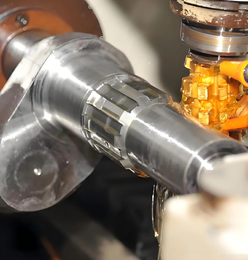
CNC boring can be carried out on both CNC lathes and CNC milling machines, but the processing principles and application scenarios of the two are very different. When boring on a CNC lathe, the workpiece rotates while the boring tool remains relatively static (only feeding along the X-axis and Z-axis). This method is essentially inner circle turning and is suitable for rotary parts such as bushings, pipe fittings, and shafts. Due to the rotation of the workpiece, dynamic balance is very important. If the workpiece is eccentric, it is easy to cause vibration and affect the processing quality.
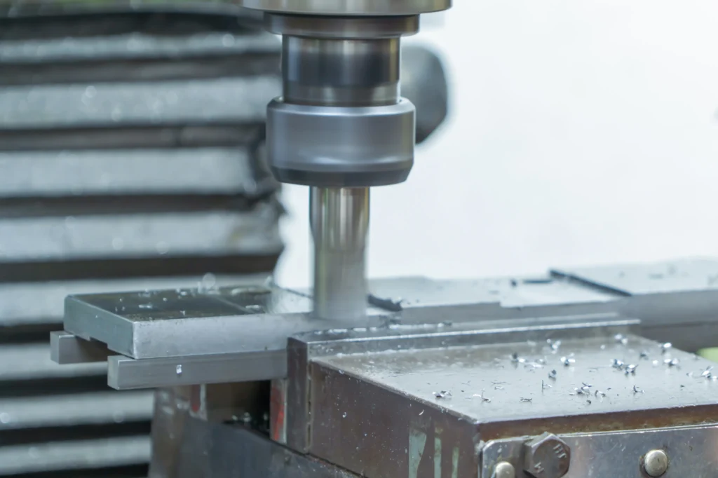
When boring on the CNC milling machine, the workpiece is fixed, and the boring tool rotates with the spindle and feeds along the axial direction. This method is more suitable for machining large box parts such as engine cylinder block and gearbox shell. At this time, the rotation balance of the tool directly determines the roundness of the hole, so the rigidity and dynamic balance of the boring bar are required. In short, the choice of which method depends mainly on the shape, size and processing requirements of the workpiece.
You Might Also Like Read:
5 Proven Ways to Reduce Cycle Time in CNC Turning Operations
CNC Milling and Turning: Which Process Do You Need?
Best CNC Lathe for Small Shops & Hobbyists (2026 Buyer’s Guide)
Comparison: CNC Drilling vs. Boring vs. Reaming
| Comparison Table: CNC Drilling vs. Boring vs. Reaming | |||
|---|---|---|---|
| Feature | Drilling | Reaming | CNC Boring |
| Primary Purpose | Create a hole | Smooth finish & Exact size | Enlarge & Straighten hole |
| Tool Type | Multi-point (Twist Drill) | Multi-point (Reamer) | Single-point (Boring Bar) |
| Adjustability | Fixed size | Fixed size | Highly adjustable |
| Correction Ability | Cannot fix hole position | Follows existing hole | Can correct hole position |
What are the Key Tools Used in CNC Boring?
In order to achieve Precision Machining, it is necessary to choose the right tool.
1. Boring Bars
The boring bar is a cantilever arm used to clamp the cutting blade. The ratio of length to diameter (L: D Ratio/length-diameter ratio) is the most critical factor in CNC Boring.
Steel Bars: Suitable for L:D ratios up to 4:1.
Carbide Bars (cemented carbide boring bar): stronger rigidity, suitable for up to 6:1 ratio.
Damped Bars: Vibration-absorbing boring bar for deep hole boring (ratio 10:1 or higher).
2. Boring Heads
Boring Heads are mainly used for milling machines. Boring heads hold the boring bar and allow fine radial adjustment. The current digital boring head allows the operator to adjust the diameter in units of 0.0001 inches without removing the tool from the spindle.
3. Inserts (blade)
Inserts are cutting tips. For CNC Lathe operations, the positive rake blade is usually preferred to reduce the cutting pressure, thereby minimizing deflection.
What are Common Issues Faced During CNC Boring in Machining?
The common problems faced by CNC boring in machining are usually due to tool instability, improper cutting parameters or poor chip management. From the technical perspective of 2026, solving these problems requires the combination of mechanical adjustment of machine tools and advanced tool technology.
1. Vibration and Chatter
Vibration and chatter are the most common machining obstacles, which are mostly caused by too long tool overhang or insufficient rigidity of machine tools.
In response to this problem, the following measures can be taken:
First, minimize the overhang as much as possible, minimize the distance between the boring bar and the tool handle, and ideally the aspect ratio (L/D) should be controlled within 3:1 .
Secondly, for processing scenes with high aspect ratio (such as 6:1 or more), a special anti-vibration boring bar with tuned mass damper or heavy metal structure can be used.
Furthermore, if chatter occurs during the machining process, the cutting speed can be reduced by 50 % to 70%, or the feed speed can be appropriately increased to keep the tool under constant load; in addition, the use of a smaller tip radius or a sharper cutting edge can also effectively reduce the radial cutting force, thereby suppressing vibration.
2. Poor Surface Finish
Rough finishes often result from dull tools, inadequate chip evacuation, or improper feed rates.
Fixes:
- Optimize Feed Rate: Use a feed rate between 0.1 to 0.2 mm/rev as a starting point. Ensure the feed is at least 25% of the insert’s nose radius to avoid “rubbing”.
- Coolant Strategy: Use high-pressure, through-tool coolant to flush chips away and prevent them from scratching the bore surface.
- Increase Speed: For finishing passes, a higher spindle speed combined with a shallow depth of cut typically produces a smoother surface.
3. Size Inaccuracy and Taper Problem
In boring processing, the boring bar is easy to cause taper or eccentricity of the hole due to force bending (deflection).
Solutions to this problem include:
- Replace the ordinary steel boring bar with a solid carbide rod, the stiffness is significantly improved, and the deflection can be reduced by up to 50%.
- Step-by-step boring is used to replace single heavy cutting with multiple light cutting finishing passes, thereby reducing tool load and improving machining accuracy.
- Application of digital boring head-the use of digital boring head that can be adjusted in micron level to ensure that the machining process always maintains strict tolerance requirements.
4. Excessive Tool Wear Problem
When machining hard materials such as Inconel and stainless steel, the cutting edge is easy to be passivated quickly.
Effective measures to extend tool life include:
- The Use of Advanced Coating Technology: The use of blades with TiAlN, TiCN or CVD diamond coatings significantly enhances heat resistance.
- Reasonable Reduction of Cutting Speed: by reducing the cutting speed to control the heat generated during the processing of hard or abrasive materials.
- Implement Real-time Monitoring: With the tool life monitoring function of the CNC system, the tool wear is dynamically tracked and replaced in time before the tool fails.
5. Inadequate Chip Evacuation
Deep or blind holes often trap chips, leading to tool jams or catastrophic breakage.
Fixes:
- Chip Breaker Geometry: Select inserts with aggressive chip breakers designed to create small, manageable “comma-shaped” chips.
- Through-Spindle Coolant: Direct coolant specifically to the cutting zone at high pressure to force chips out of the bore.
Conclusion
Whether you’re correcting deflected drilling, meeting strict ISO tolerances, or ensuring concentricity on CNC lathe, the principles are the same: rigidity comes first, tool geometry comes second.
By choosing the right overhang length, management speed and feed, and understanding the difference between drilling and boring, you can completely change your machining operations.
If you want to know more about drilling,you can check JIANKE.com to read CNC Drilling: 7 Best Tips for Achieving High Precision.