The correct setting of machine tools is the key to processing high-precision parts or scrapped parts. For mechanics and operators, mastering the setup process for CNC lathe – especially tool offsets and work offsets – is an essential skill to ensure accuracy, safety and efficiency.
Whether you operate a Haas, Fanuc or Mazak control, the core principles of telling the machine where the tool is and where the part is are the same. In this article, we will explain in detail how to set up a CNC lathe that covers everything from geometric offsets to the creation of zeros for G54 work.
What is a CNC lathe?

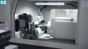
Before diving into the technical setup, you need to understand the architecture of the machine. CNC lathe (Computer Numerical Control lathe) is a machine tool that rotates the workpiece around the rotating shaft. It is used to perform various operations such as cutting, grinding, knurling, drilling, end face processing and turning.
Unlike milling machines where the tool rotates, in CNC lathes, parts are rotating while the tool remains stationary (unless a powered tool holder is used). This difference makes the setting of X-axis (diameter) and Z-axis (length) crucial for accuracy.

Why is Proper Setting Important?
Improper CNC lathe setup can lead to:
- Dimension Error: Parts do not meet the tolerance requirements.
- Poor Surface Finish: Vibration or chatter caused by too long tool extension or loose fixture.
- Machine Crashes: The most dangerous consequence, it can lead to damage to the turret or spindle and high maintenance costs.
Essential Tools for CNC Lathe Setup
In order to set up correctly, make sure the following tools are ready:
- Edge Finder or Dial Indicator: For manual tool setting or correction.
- Micrometer or Vernier Caliper: Used to measure the diameter of the blank.
- Paper or Feeler Gauge: For the ‘touch-off’ method (if not using a probe).
- Tool Eye/Q-Setter: If your machine is equipped with an automatic tool setting arm.
How to Set Tool Offset on CNC Lathe
The machine knows where its own home position is, but it doesn’t know the length or diameter of the tool you just put into the turret. Tool offset is used to fill this information gap.
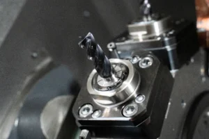
Step 1: Install the Tool
The cutting tool is firmly loaded into the tool tower. Ensure that the blade is new and tighten the tool according to the correct torque specifications.
Step 2: Establish Z-axis Offset (Length)
Switch to Handwheel/Click Mode: Manually move the turret close to the workpiece.
Face the Part: Start the spindle, perform slight end face cutting and cut out a clean plane.
Do Not Move the Z-axis: In the case of not moving the Z-axis, only the X-axis is used to remove the tool from the workpiece.
Measurement and Input: Enter the CNC lathe control panel (usually under the ‘Offsets’ or ‘Geometry’ tab). Select the tool number corresponding to the tool position.
Tool Off: Enter Z0 and press ‘Measure’ or ‘Tool Measure’. The machine tool now knows that for this particular tool, the tool tip is located right at the end face of the part (Z0).

Step 3: Establish X-axis Offset (Diameter)
Cut a Diameter: The moving tool is cut on the outer circle (OD) of the blank.
Keep the X Position: Stop the spindle, but don’t move the X axis. Only the Z-axis is used to withdraw the tool.
Measure the Part: Use a micrometer to measure the diameter (e.g. 2.500 inches) that has just been cut.
Input Data: On the offset page, highlight the X axis of the tool.
Teach the Machine: Enter X 2.500 (or the actual value you measured) and press ‘Measure’. CNC lathes now understand the distance from the center of the turret to the tip in the diameter direction.
Pro tip : If your machine is equipped with a tool presetter arm (Tool Eye), you can simply drop the tool arm, contact the tip with the sensor, and automatically calculate these geometric offsets.
Understand Work Zeros (G54) on CNC lathes
Once the machine knows the size of the tool, it also needs to know the position of the part in the 3D space. This is the zero point of the workpiece, commonly known as G54, G55, etc.
Why Do We Need Work Zero?
The coordinate system of CNC lathe must be aligned with the coordinate system in the G code program. The program origin (0,0) is located at the center of the rotating shaft (X0) and the front surface of the finished part (Z0).
How to Set the G54 Work Offset?
Select the Master Tool: Select a tool that you have set the geometric offset (usually a cylindrical rough turning tool).
Touch the End Face: Manually move the tool until it gently touches the end face of the workpiece ( or use the stopper method to slide a piece of paper between the tool and the part until it feels resistant ).
Navigate to Work Offsets: Go to the ‘Work Offsets’ page on the controller.
Input Z Value: Move the cursor to the G54 Z axis, input Z0 and press ‘measure’.
If you plan to turn 0.020 inches of material in the machining cycle, you can set it to Z0.020 so that the machine knows there is still room for surplus.
For more in-depth understanding of G code and coordinate system, please see the guide on the G-code programming Basics.
Geometry Offsets vs. Wear Offsets
When operating a CNC lathe, you will see two columns in the offset page: Geometry and Wear.
Geometry Offsets: These are large values representing the physical distance from the mechanical origin to the tool tip. These are determined during the above initial setup.
Wear Offsets: These are used for fine-tuning. If the measured value of the part is 0.001 inches larger due to blade wear, you should enter−0.001′ in the wear offset. Usually, the geometric offset should not be changed for minor adjustments.
| Comparison Table: Manual Touch-Off vs. Tool Eye | ||
|---|---|---|
| Feature | Manual Touch-Off | Tool Eye (Probe) |
| Accuracy | High (depends on operator skill) | Very High (consistent) |
| Speed | Slow (requires cutting/measuring) | Fast (touch sensor) |
| Risk | Lower risk of sensor damage | Risk of breaking probe arm |
| Best For | Job shops, older machines | High production, newer machines |
Common Mistakes When Setting Up a CNC Lathe
Even experienced mechanics may make mistakes. Here are the most common pitfalls to avoid:
Forgetting to Call the Tool Number
Before tool setting, make sure that the current tool number in the controller matches the physical tool in the turret. If the machine thinks it is using the No. 2 cutter, and you are setting the geometric parameters of the No. 1 cutter, it will cause a crash.
Confusing Radius & Diameter
The X-axis of most CNC lathe control systems operates in diameter mode, but some older systems or specific parameters may use radius mode. Be sure to confirm which mode your machine is in. If you enter the radius value on the diameter mode machine tool, the size of the part will be only half of the expected size.
Neglecting the Tip Nose Radius
The theoretical tip is a sharp point, but the actual inserts have rounded corners (e.g., R0.4 or R0.8). In order to perform precise chamfering and arc machining, you must enter the correct tool nose radius (TNR) and tool nose orientation in the offset page for the machine tool to apply tool nose radius compensation (G41/G42).
For more insights on machining strategies, you can read our internal guide [ CNC Milling and Turning: Which Process Do You Need?]
Conclusion
Mastering the setup of CNC lathes is the first step to becoming a skilled mechanic. By correctly establishing the tool geometry offset and the work zero point coordinates, you can ensure that the machine fully interprets your code as intended. Please remember to verify the measurement results, carefully check the current tool number, and always be cautious when running the first part of the new setup (using single-segment mode).
Through the above steps, you can confidently convert raw materials into precision parts.